Analysis Summary
This website section offers a detailed look at the extensive assessments carried out on the suspension and steering components of the RC Baja Car. These analyses break down the precise functions of each part, shedding light on their critical roles in meeting the car's demanding requirements. Furthermore, the section thoroughly explores the design decisions made to guarantee exceptional performance and compliance with the RC Baja Car's needs.
Requirements
1. The suspension must be able to deflect an eighth of an inch.
2. The suspension must be able to absorb bumpy terrain at 10 mph.
3. The suspension must allow the ride height to be at least half an inch off the ground.
4. The suspension must be able to handle a speed of 10 mph with a 1.5 safety factor for the speed.
5. The suspension must be able to absorb 20 pounds of force.
6. There must be independent suspensions for all four wheels.
7. The car will be able to withstand a drop test from a height of 2.5 feet.
8. The front steering must be able to rotate at least 10 degrees left and right.
9. The steering components must be able to absorb 10 pounds of force.
10. The steering components must be able to maintain durability at 10 mph with a 1.5 safety factor for the speed.
11. The steering components must be able to stay in a straight at 10 mph with a 1.5 safety factor for the speed.
12. The steering must be able to function at 10 mph, with a 1.5 safety factor for the speed, on rough and bumpy terrain.

Spring Constant & Force Analysis
The spring analysis helped identify the spring constant that it would experience under a ten-pound load. Once the spring constant was found, the value was used to find the force that the spring would experience under the load to ensure that the spring will not fail.
Turn Radius Analysis
This analysis focused on the required steering angle that was needed to ensure that the car was able to turn 180 degrees based off of the cars dimensions. Based off of the calculation using trigonometry it was found that the turning radius that the car would have is 30 degrees.


Diameter of Upper Control Arm
The analysis for the upper control arm was aimed to find the diameter based on the requirements for the car. The analysis was conducted by finding the moment of inertia with an assumed weight for the rod and using that value to find the radius. The radius was found equaling a value that is less than the required deflection to the deflection equation for a beam with a force in the center. After careful calculations it was determined that the final diameter should be an eighth of an inch.
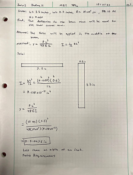
Lower Control Arm Deflection
The focus of this analysis was to ensure that the deflection of the lower control would be less than the required 16th of an inch. After using predetermined measurements for the length, width, and height of the lower control arm it was determined that the deflection was less than a 16th of an inch.

Push Rod Bolt Analysis
The aim of this analysis was to determine whether or not the dowel pin will be able to support the mounts for the upper and lower control arms. This piece is vital for the car's functionality because it allows the control arms to move in a vertical direction. The analysis additionally determined that it will support the required 20-pound load. After determining whether the 1/8th-inch 4037 Alloy Steel down pins would work, it was decided that these components would be purchased and implemented into the car's final design for complete construction.